Inverse Kinematics
Inverse kinematics (IK) allow us to determine the required joint angles of a robot given the desired position of the end-effector.
Recommended Pre-Reading
Before reading this, you should familiarise yourself with Forward Kinematics.
Inverse kinematics (IK) is a hard problem, a solution may not exist or may not be unique. This is because the IK problem is nonlinear and there are no general methods of solving nonlinear equations.
One reason for a potential lack of solutions is algebraic; this is essentially a lack of degrees of freedom (DoF). A solution to the IK problem requires enough DoF. Issues can also arise relating to the workspace of the robot. If the specified pose of the end-effector is outside of the workspace, no solution can exist.
Generally, arbitrary positioning and orientation of an end-effector in 3D space requires 6 DoF
Typically kinematic equations are nonlinear. There are no general methods of solving nonlinear equations, and thus, even if a solution exists it may not be unique. In addition, if a robot is kinematically redundant, there will always be multiple solutions to their IK equations.
Degeneracy
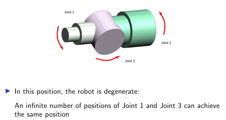
Degeneracy is an extreme case of redundancy where a robot has an infinite number of IK solutions.
 A diagram of a degenerate joint
Resolving Multiple Solutions
While redundancy in manipulators may be advantageous in some respects, for a real robot this needs addressing. How do we get the computer to choose the “right” solution?
There are two main approaches to this:
- Constraints
- Hardware constraints on joints often exist; these effectively eliminate some solutions
- e.g. constraining manipulator angle $\tilde{\theta}_2\in[0,\pi]$ eliminates $(\tilde{\theta_1},\tilde{\theta_2})$ solutions
- Software constraints to guide the solutions
- Hardware constraints on joints often exist; these effectively eliminate some solutions
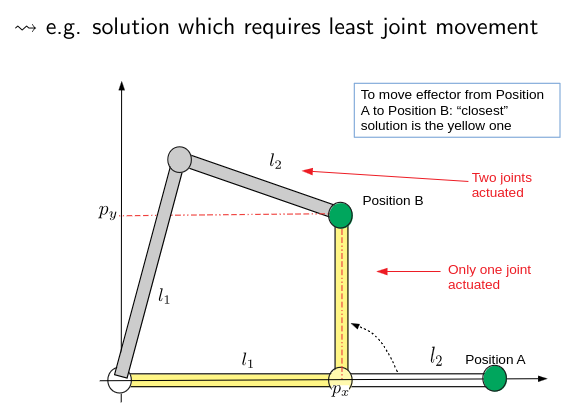
But robots are rarely static, and IK is used to move a robot from position A to position B. If the kinematics equation of position B has multiple solutions, pick the one closest to position A.
 A diagram of selecting the closest IK solution
$\arctan$
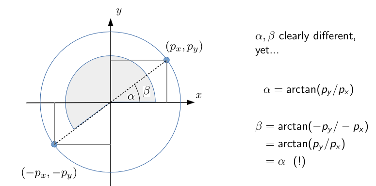
Many analytical IK equations feature the $\arctan(\cdot)$ function; the range of $\arctan$ is $(-\frac{\pi}{2},\frac{\pi}{2})$ and thus often not satisfactory.
Replace $\arctan(\cdot)$ with the double argument $\text{atan2}(\cdot,\cdot)$. This prevents the symmetry and infinity issues with $\arctan$.
\[\text{atan2}(y, x) = \begin{cases} \arctan\left(\frac{y}{x}\right) & x > 0 \\ \arctan\left(\frac{y}{x}\right) + \pi & x < 0, y \geq 0 \\ \arctan\left(\frac{y}{x}\right) - \pi & x < 0, y < 0 \\ \frac{\pi}{2} & x = 0, y > 0 \\ -\frac{\pi}{2} & x = 0, y < 0 \end{cases}\]From now on, interpret $\arctan$ as $\text{atan2}$.
From FK to IK
There is an alternative way to represent FK. The symbolic way would be:
\[\begin{bmatrix}p_x\\p_y\\p_z\\\phi\\\theta\\\psi\end{bmatrix}=f\begin{pmatrix}\begin{bmatrix}q_1\\q_2\\\vdots\\q_n\end{bmatrix}\end{pmatrix}\qquad f(.):\mathbb{R}^n\mapsto\mathbb{R}^6\]The process of solving IK is therefore reversing this relationship.
\[\begin{bmatrix}q_1\\q_2\\\vdots\\q_n\end{bmatrix}=f^{-1}\begin{pmatrix}\begin{bmatrix}p_x\\p_y\\p_z\\\phi\\\theta\\\psi\end{bmatrix}\end{pmatrix}\qquad f^{-1}(.):\mathbb{R}^6\mapsto\mathbb{R}^n\]IK is finding $f^{-1}$ (if it exists).
IK Assumptions
We will assume that a solution exists, and therefore we must assume:
- The end-effector motion is feasible (inside the workspace)
- There are enough DoF present
Categories of IK Solutions
There are two main categories of IK solutions:
- Analytical methods provide symbolic solutions to the IK problem. Typically such solutions are valid for all (or almost all) values of the end-effector motion.
- Numerical methods provide particular solutions for certain values.
Analytical Solutions
Analytical solutions are derived using mathematical techniques to find exact solutions to the IK problem. There are two main categories of analytical solutions.
Algebraic
One states a desired form of T-matrix and then equates this to the FK expression.
\[T_{\text{des}}=~^n_0T(q_1,q_2,\dots,q_n)\]This gives a set of equations (ostensibly 12, but normally fewer) which need solving for the unknowns $q_1,\dots,q_n$.
- Specify the desired T-matrix for the end-effector
- Equate this to the T-matrix resulting from the FK equations
This gives 12 equations in the unknown parameters in the vector $q=[q_1\dots q_n]’$:
\[\begin{align*}\tilde{r_{11}}&=r_{11}(q)\\\tilde{r_{12}}&=r_{12}(q)\\\vdots~~&=~~\vdots\end{align*}\]The equation matrix is often reduced: DH representation; R-matrix orthogonal
Geometric
One can also decompose the IK problem into a set of planar geometry problems which are typically easy to solve but sometimes require some creativity.
- Decompose the IK problem into a number of planar geometry problems
- Solve these using basic geometry
This approach is straightforward but often quite intricate.
Numerical Methods
There are also subcategories of numerical methods for solving IK problems.
We will not go into detail about these methods.
Iterative
Normally involves expanding $f(.)$ with a Taylor series and refining the initial solution. Various algorithms of this type are implemented in Matlab.
“Intelligent” methods
Various techniques such as NNs, fuzzy logic, and particle swarm optimisation (PSO) can be harnessed to solve the IK problem. This can be quick but unreliable.
