Transformations
This guide will provide a brief overview on how reference frames transform as we move through a kinematic chain. These concepts are necessary before moving on to more advanced kinematics guides.
For reasons you will see later, this guide will focus on manipulator robots, but the ideas are transferrable to other morphologies.
Recommended Pre-Reading
Before reading this, you should have some familiarity with matrices and algebra.
Kinematic Chains
Robot manipulators (arms) can be thought of chains of reference frames, or kinematic chains. The transformation for a reference frame is entirely dependent on the previous frame.
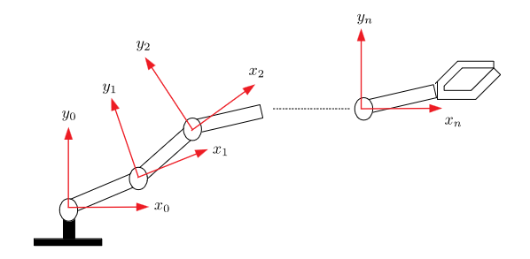 Example kinematic chain
It is easy to determine the $i$th joint position w.r.t. the $i-1$th reference frame, therefore the end-effector position is determined by traversing the chain:
\[{}^0_nT={}^0_1T\,{}^1_2T\,\cdots\,{}^{n-1}\_nT\]Where $^{i-1}_iT$ is the transformation matrix from link $i-1$ to link $i$. In other words the rotation and displacement of frame $i$ w.r.t. frame $i-1$
2D Transformations
To begin, we will look at only two dimensions. Once we have gone over the basics, we can extend to the three dimensions of the real world.
Translation
Consider the below image.
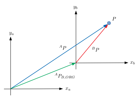 Abstract 2D translation
There exists some particle $P$ with two coordinate frames ${A}=(x_a, y_a)$ and ${B}=(x_b,y_b)$. $^AP_{B,\text{ORIG}}$ is the origin of ${B}$ w.r.t. ${A}$. The position of the particle in frame $Q$ is defined as $^QP$.
If we know the position of the particle in frame $B$, we can find the position of $P$ in frame $A$, $^AP=~^AP_{B,\text{ORIG}}+~^BP$, where $^AP_{B,\text{ORIG}}$ is a translational mapping from ${A}$ to ${B}$.
Rotation
We can use a similar approach for calculating the rotation between two reference frames.
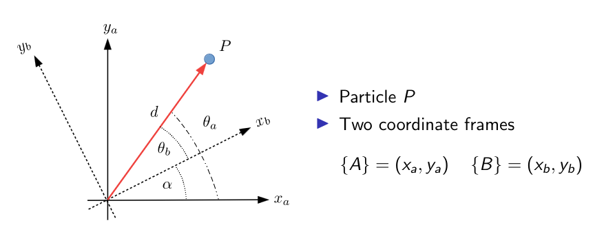 Abstract 2D rotation
Firstly, we must define our two frames,\(\{A\}\) and \(\{B\}\). The position vector w.r.t. \(\{A\}\) is \(^AP=d\begin{bmatrix}\cos\theta_a \\ \sin\theta_a\end{bmatrix}\); and for \(\{B\}\), \(^BP=d\begin{bmatrix}\cos\theta_b \\ \sin\theta_b\end{bmatrix}\).
It is worth noting that \(\theta_a=\alpha+\theta_b\).
We can use this information to find an equation to rotate the position vector between frames.
\[\begin{align*} ^AP&=d\begin{bmatrix}\cos(\theta_b+\alpha)\\\sin(\theta_b+\alpha)\end{bmatrix}\\&=d\begin{bmatrix} \cos\theta_b\cos\alpha-\sin\theta_b\sin\alpha\\ \sin\theta_b\cos\alpha+\cos\theta_b\sin\alpha \end{bmatrix}\\&= \begin{bmatrix} \cos\alpha & -\sin\alpha\\\sin\alpha&\cos\alpha \end{bmatrix}d\begin{bmatrix}\cos\theta_b\\\sin\theta_b\end{bmatrix}\\ &= \begin{bmatrix} \cos\alpha & -\sin\alpha\\\sin\alpha&\cos\alpha \end{bmatrix}~^BP \end{align*}\]The matrix \(^A_BR=\begin{bmatrix}\cos\alpha&-\sin\alpha\\\sin\alpha&\cos\alpha\end{bmatrix}\) is a rotation matrix for the rotation of the axes of ${B}$ by $\alpha$ (anti-clockwise) from ${A}$
Succinctly, we can write this as \(^AP=~^A_BR~^BP\).
Homogeneous Transformations
We can combine translations and rotations into a single operation called a homogeneous transformation.
If a coordinate frame \(\{B\}\) is translated by the vector \(^AP_{B,\text{ORIG}}\) from \(\{A\}\) and also rotated by an angle $\alpha$ anti-clockwise, if we know the position of a particle in \(\{B\}\) we can express it in \(\{A\}\)
\[^AP=~^AP_{B,\text{ORIG}}+~^A_BR~~^BP\]This can be expressed in matrix form as
\[^AP=\begin{bmatrix}^A_BR&^AP_{B,\text{ORIG}}\end{bmatrix}\begin{bmatrix}^BP\\1\end{bmatrix}\]This above matrix is not square and so not invertible, so we can augment it as
\[\begin{bmatrix}^AP\\1\end{bmatrix}=\begin{bmatrix}^A_BR&^AP_{B,\text{ORIG}}\\0&1\end{bmatrix}\begin{bmatrix}^BP\\1\end{bmatrix}\]By defining \(^A\tilde{P}:=\begin{bmatrix}^AP\\ 1\end{bmatrix}\) and \(^B\tilde{P}:=\begin{bmatrix}^BP\\ 1\end{bmatrix}\) we have \(^A\tilde{P}=~^A_BT~~^B\tilde{P}\) where \(^A_BT=\begin{bmatrix}^A_BR&^AP_{B,\text{ORIG}}\\0&1\end{bmatrix}\)
Homogeneous Transformation: the matrix \(^A_BT\) is the so-called homogeneous transformation matrix which expresses the transformation between the frame \(\{B\}\) and \(\{A\}\).
The matrices of \({}^A_BT\) can be expanded to produce the matrix
\[{}^A_BT=\left[ \begin{array}{c c|c} \cos \alpha & -\sin \alpha & ({}^A P_{B,\text{ORIG}})_x \\ \sin \alpha & \cos \alpha & ({}^A P_{B,\text{ORIG}})_y \\ \hline 0 & 0 & 1 \\ \end{array} \right]\]3D Transformations
The method for 3D transformations is similar to that in 2D, just with an extra dimension!
Translation
Consider the below image.
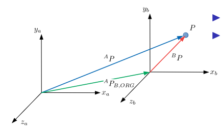 Abstract 3D translation
For some particle $P$ there are two coordinate frames:
\[\begin{align*} \{A\}&=(x_a,y_a,z_a)\\ \{B\}&=(x_b, y_b, z_b) \end{align*}\]Similarly, $^AP_{B,\text{ORIG}}$ is the origin of ${B}$ w.r.t. ${A}$.
We can use this to map between frames, $^AP=~^AP_{B,\text{ORIG}}+~^BP$. Therefore, $^AP_{B,\text{ORIG}}$ is a translational mapping from ${B}$ to ${A}$, and $^AP$ and $^BP$ are the positions of the particle in the respective frames.
Rotation
Rotations are fundamentally more difficult in 3D than in 2D.
- There are three axes which can be rotated around
- These axes can either be fixed (static) or move with each rotation (non-static)
- The order of rotation, while philosophically unimportant, is of vital importance for consistency
- The rotation matrix formed by rotation in a particular order is not the same as the rotation matrix for a different order
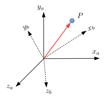 Abstract 3D rotation (both frames are right-handed with coincident origins)
Expressing \(\{B\}\) w.r.t. \(\{A\}\) requires rotation around three axes in general. The order of rotation is important, there is not a single unique mapping between the two frames.
Intrinsic vs. Extrinsic Rotation
This is also referred to as non-static/relative vs. static rotation.
For intrinsic/relative rotation, rotation is done around intermediate reference frames, and the rotation matrices are post-multiplied; this means that the first rotation matrix in the expression is the first rotation in the sequence.
For extrinsic/static rotation, all rotation is done around a fixed reference frame, and rotation matrices are pre-multiplied; this means the first rotation matrix in the expression is the last rotation in the sequence.
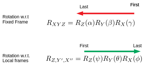 A comparison between intrinsic and extrinsic rotations
Extrinsic Rotation
A common way to rotate in 3D is the “fixed X-Y-Z” way:
- Rotate about the X-axis (fixed)
- Rotate about the Y-axis (fixed)
- Rotate about the Z-axis (fixed)
This yields the rotation matrix $^A_BR_{XYZ}(\alpha, \beta,\gamma)=R_Z(\alpha)R_Y(\beta)R_X(\gamma)$
The individual rotation matrices are
\[\begin{aligned} R_Z(\alpha) &= \begin{bmatrix} \cos\alpha & -\sin\alpha & 0 \\ \sin\alpha & \cos\alpha & 0 \\ 0 & 0 & 1 \end{bmatrix}\\ R_Y(\beta) &= \begin{bmatrix} \cos\beta & 0 & \sin\beta \\ 0 & 1 & 0 \\ -\sin\beta & 0 & \cos\beta \end{bmatrix}\\ R_X(\gamma) &= \begin{bmatrix} 1 & 0 & 0 \\ 0 & \cos\gamma & -\sin\gamma \\ 0 & \sin\gamma & \cos\gamma \end{bmatrix} \end{aligned}\]When combined together, it looks something like this
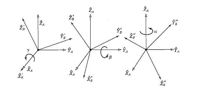 Extrinsic rotation diagram
The combined rotation matrix is
\[{}^A_B R_{XYZ}(\alpha, \beta, \gamma) = \begin{bmatrix} \cos\alpha \cos\beta & \cos\alpha \sin\beta \sin\gamma - \sin\alpha \cos\gamma & \cos\alpha \sin\beta \cos\gamma + \sin\alpha \sin\gamma \\ \sin\alpha \cos\beta & \sin\alpha \sin\beta \sin\gamma + \cos\alpha \cos\gamma & \sin\alpha \sin\beta \cos\gamma - \cos\alpha \sin\gamma \\ -\sin\beta & \cos\beta \sin\gamma & \cos\beta \cos\gamma \end{bmatrix}\]Intrinsic Rotation
The general idea is to rotate successively into intermediate (relative) reference frames
- Perform one rotation
- This rotation establishes a new frame
- Perform another rotation
- This rotation establishes a new frame
- Perform a final rotation
This can be denoted $^A_BR=~^A_{B’}R~^{B’}_{B^{\prime\prime}}R~^{B^{\prime\prime}}_BR$
As before, the rotation matrix comprises of a product of rotation matrices and must be carried out in a specific order.
There are various different conventions, we will use $Z$-$Y$-$X$ Euler Angles.
 Intrinsic rotation diagram
Noting that we rotate about the intermediate axes $Y’$ and $X’’$
\[^A_BR_{ZY'X''}(\psi, \theta,\phi)=R_Z(\psi)R_{Y'}(\theta)R_{X''}(\phi)\]Where our rotation matrices are
\[\begin{aligned} R_Z(\psi) &= \begin{bmatrix} \cos \psi & -\sin \psi & 0 \\ \sin \psi & \cos \psi & 0 \\ 0 & 0 & 1 \end{bmatrix}\\ R_Y(\theta) &= \begin{bmatrix} \cos \theta & 0 & \sin \theta \\ 0 & 1 & 0 \\ -\sin \theta & 0 & \cos \theta \end{bmatrix}\\ R_{X''}(\phi) &= \begin{bmatrix} 1 & 0 & 0 \\ 0 & \cos \phi & -\sin \phi \\ 0 & \sin \phi & \cos \phi \end{bmatrix} \end{aligned}\]The rotation matrices have the same form as in fixed axis rotation but the axes about which the rotation takes place are different.
This gives an overall rotation matrix of
\[R_{Z'X''Y''}(\psi, \theta, \phi) = \begin{bmatrix} \cos\psi\cos\theta & \cos\psi\sin\theta\sin\phi - \sin\psi\cos\phi & \cos\psi\sin\theta\cos\phi + \sin\psi\sin\phi \\ \sin\psi\cos\theta & \sin\psi\sin\theta\sin\phi + \cos\psi\cos\phi & \sin\psi\sin\theta\cos\phi - \cos\psi\sin\phi \\ -\sin\theta & \cos\theta\sin\phi & \cos\theta\cos\phi \end{bmatrix}\]Homogeneous Transformations
Similar to in 2D, homogeneous transformations provide a way of combining rotations and translations
As with 2D, given a position w.r.t. frame \(\{B\}\) the position w.r.t. frame \(\{A\}\) can be obtained via
\[^AP=~^AP_{B,\text{ORIG}}+~^A_BR~~^BP\]Where \(^AP_{B,\text{ORIG}}\) is a vector describing a translation of the origin of frame \(\{B\}\) in \(\{A\}\) coordinates. \(^A_BR\) is a rotation matrix describing a rotation of the \(\{B\}\) axes w.r.t. frame \(\{A\}\)
Homogeneous transformations in 3D are given by
\[\begin{align*} ^AP&=\begin{bmatrix}^A_BR&^AP_{B,\text{ORIG}}\end{bmatrix}\begin{bmatrix}^BP\\1\end{bmatrix}\\ \implies \begin{bmatrix}^AP\\1\end{bmatrix}&=\begin{bmatrix}^A_BR&^AP_{B,\text{ORIG}}\\0&1\end{bmatrix}\begin{bmatrix}^BP\\1\end{bmatrix}\\ \implies ^A\tilde{P}&=~^A_BT~~^B\tilde{P} \end{align*}\]Where
\[^A_BT=\begin{bmatrix}^A_BR&^AP_{B,\text{ORIG}}\\0&1\end{bmatrix}\]This can be expanded to
\[{}^A_BT = \begin{bmatrix} \cos\alpha \cos\beta & \cos\alpha \sin\beta \sin\gamma - \sin\alpha \cos\gamma & \cos\alpha \sin\beta \cos\gamma + \sin\alpha \sin\gamma & {}^BP_x\\ \sin\alpha \cos\beta & \sin\alpha \sin\beta \sin\gamma + \cos\alpha \cos\gamma & \sin\alpha \sin\beta \cos\gamma - \cos\alpha \sin\gamma & {}^BP_y\\ -\sin\beta & \cos\beta \sin\gamma & \cos\beta \cos\gamma & {}^BP_z \\ 0 & 0 & 0 & 1 \end{bmatrix}\]Items to note about 3D homogeneous transformation matrices:
- 4x4 matrix describing rotation/translation
- 9 entries describing rotation; 3 describing translation
- The basis of most kinematics equations
Similar to 2D, we find that $^A_BT=~^A_CT~~^C_BT$. This transfers directly to our robotics applications in that $^0_nT=^0_1T\dots~^{n-1}_nT$ (c.f. kinematics chain image at the start of this page).